
RC Baja Buggy
Drivetrain & Chassis
Analysis
The analysis for the components was calculated based on the maximum capability to ensure it meets the requirement and more. Free body diagram, along with statics and dynamics were applied to calculate the forces exerted on both chassis and drivetrain, confirming they delivered the necessary power and support. The application of mechanics of material was applied to decide if the material and design of the component was used to determine if the component was robust enough to withstand operational stresses and prevent any possibility of failure.
Requirements
-
One propulsion motor with a power output of 250 watts which drives the whole vehicle. One 5200mAh battery per vehicle that lasts longer than 20 mins.
-
Being able to operate the vehicle within a range of 20 meters.
-
The drivetrain on the vehicle will be sustainable at a speed of 25 miles per hour.
-
The bumper attached to the vehicle must take a frontal impact of 15lb with minimal damage.
-
The plastic body ornament for the RC Baja buggy will use 4 mounting points to be attached.
-
The driveshaft will contain a slip joint in the center, and it will extend at least 15mm in both directions, for a total of 30mm of travel.
-
The overall length of the vehicle will be less than 20 inches and the overall width will be less than 12 inches.
-
Adjustable motor mount with 1/4 inches of play for adjustment.
-
The electric motor with a power output of 1850 watts.
-
Off-roading tires with appropriate tread patterns for rough terrain, should be 1/8 scale wheels.
-
3D Printed PLA+ chassis frame weighing 2.5 lb.
-
Chassis deflection no more than half of inch with 20lbs.
-
Bumper deflection is no more than half of an inch.
-
The gear prop shaft must withstand 5lb of torque.
-
Flexure in axel strength is 60MPas
-
Have at least a 5:1 Gear ratio.
-
The heat produced by the bearing does not exceed the temp of 35 degrees Celsius.
-
The vehicle must survive 2 feet on the drop test.
-
Accelerate to 20 mph in less than 10 seconds.
Analysis 1: Maximum Motor Power

The purpose of analysis 1 was to find the maximum motor power for the Trackstar 1/10 brush-less motor. This determines the power output is 239.76W.
Figure 2.01
Analysis 2: Maximum Speed

The purpose of analysis 2 was to find the maximum speed it is capable of with a 4 inch diameter wheel. The maximum speed is 63.76 MPH with a 1:1 ratio.
Figure 2.02
Analysis 3: Chassis Deflection
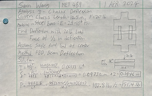
The purpose of analysis 3 was to find the chassis deflection of a 1/8-inch thick steel connecting bar. It was determined the deflection of the plastic was 0.1946 inches with a 20 lb load and at max deflection of 1/2 inch, the load was 51.4 lb.
Figure 2.03
Analysis 8: Acceleration

The purpose of analysis 8 was to find the acceleration capability of the motor and vehicle. In the analysis, the calculated value for the acceleration was 7.334 ft/s^2, where as the requirement was 2.93 ft/s^2. This shows that the vehicle is capable of reaching that acceleration no problem.
Figure 2.08
Analysis 9: Friction Heat from Bearing

The purpose of analysis 9 was to find the heat produced by the bearing when rotating 22496 rpm. Using frictional torque and the heat transfer equation, with 10 minutes runtime the temperature produced was 0.281 degrees Celsius. This was important because the housing is made out of plastic and deformation from heat is crucial.
Figure 2.09
Analysis 10: Bumper Deformation

The purpose of analysis 10 was to find the bumper deflection under load and impact. using static loading and linear impact equation, the deflection was determined to be 0.42" with static loading at 20 lb and 3.589x10^-4" linear impact at 25 mph.
Figure 2.10
Analysis 12: Gear Ratio and Motor Torque

The purpose of analysis 12 was to find the gear ratio and motor torque that was suitable for the acquired motor. There are two different sets of gearing ratios completed. The first two gear sets came out to 9.3 as the velocity ratio. The second two-gear set came out to 8.38. The new top speed calculated with the train value came out to be 27.24 mph and 30.27 mph. The calculated maximum torque came out to be 1.33 N-m and 1.2 N-m.
The reason for the two sets is because the motor housing is adjustable and this allows the two different gears, 18T and 20T to be in place. The 18T was mainly used because it puts less stress on the motor and the top speed is more than sufficient for the requirements.
Figure 2.12