
RC Baja Buggy
Drivetrain & Chassis
Construction
This RC Baja buggy was built in a modular setting. Most of the vehicles will be constructed utilizing the 3D printing process with PLA plus plastic material. The chassis consists of two parts, front and rear. The rear chassis was the main focus of the construction because that was where the drive train sat. The vehicle is made of 16 parts and 3 sub-assemblies. All component of the vehicle was manufactured in-house or at school. The main drive shaft connecting rods were made out of plain carbon steel and they were machined at the CWU machine shop.
All the drive train and chassis component were 100% completed and operational in fall quarter ahead of class schedule. The early completion was done by rapid prototyping and manufacturing on the 3D printer. The benefit of mostly printed component was the unlimited access and time on the two Creality Ender 3 S1 printer at home, and not relying on the school printers where it had limited access and time. In the winter quarter all the components were over viewed and tested to ensure they were sustainable with good performance, any components that did not meet the standard were reviewed and upgraded.
Drawing Tree

Figure 3.1 - Drawing Tree
Manufacturing
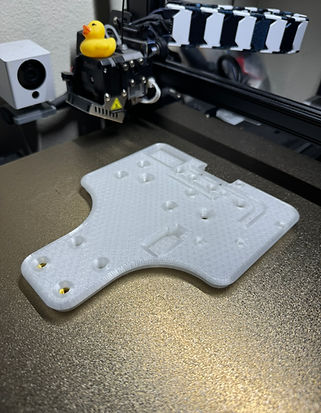
Figure 3.2 - 3D printer result on bed

Figure 3.3 - 3D printed chassis with all components
Figure 3.4 - Cosmetic upgrade
In Figure 3.2, the rear chassis was 3D printed on the Creality Ender 3 S1 with 10 layers of walls at 0.8mm and 20% of infill took 8 hours. The increased walls were to account for the threaded insert that was heated into the plastic chassis. The insert will increase the strength of the attachment system for all the components. Plastic threads can be good but with the amount of force acting on them, the brass thread will ensure no issues in operation.
In Figure 3.3, all the components fit on the chassis with no issues, and all the parts fit and run as how it was designed. Throughout the design process, the chassis was upgraded in the cosmetics and better fitment of noncomponents as shown.
In Figure 3.4. An additional under glow light with a recessed area for wire management was added to the chassis concluding the final design for the chassis.

Figure 3.5 - Drive Train Layout

Figure 3.6 - Turning Operation
Figure 3.7 - Drive train operating
In Figure 3.5, the layout of the drive train is presented. The drive shaft and connecting points were machined out of mild steel found in the machine shop at CWU and it was turned down on the lathe machine. All the other components shown were purchased on Amazon. The bevel gear is a 1:1 ratio.
In Figure 3.6, the operation of turning out the drive shaft components on the lathe machine at the machine shop. The material used is 304 stainless steel with a HSS cutting bit for turning. The HSS was not cutting well, later used carbide bit which resulted in better cutting and finish.
In Figure 3.7, the operation of the whole drive train is shown. All the components lined up and worked together to provide torque to the wheels. Upon testing the drive train by doing a burnout, the spur/pinion gear with a 21T to 86T ratio was good for the operation of the vehicle.


Figure 3.8 - Pre Etch
Figure 3.9 - Etching

Figure 3.10 - Coffee Etch

Figure 3.11 - Renaissance Sealing
In Figure 3.8, the Damascus steel was sanded down with sandpaper from 180 to 1000 grit on all sides. This process was crucial because it would ensure a better finish on the final part. Before dropping into the etch solution, all parts were cleaned with soap and water, then wiped down with 99% isopropyl alcohol to remove all the gunk and oil on the surface before dropping into the solution.
In Figure 3.9, the parts were placed in the etching solution. The solution is made out of 1 part ferric chloride and 8 part distilled water. The parts were etched for 4 hours and each hour was taken out to spray down with water so it has a clean surface to etch which will result in a cleaner and uniform etch. After the etching process, it was scrubbed with soap and water and a light scotch bright to expose the surface.
In Figure 3.10, the part was placed in the concentrated coffee solution. This method is to darken the colors of the etch so it has a more defined pattern in the final results.
In Figure 3.11, the etching process was completed and cleaned off with soap and water with a little scotch right to show the shiny surface. To seal the surface of the steel and prevent rusting, a little Renaissance wax was covered on all surfaces.


Figure 3.12 - Pre Patina
Figure 3.13 - Finished Results

Figure 3.14 - Patina Process
In Figure 3.12, the aluminum was lightly sanded and then placed in the tumbler for 4 hours to deburr and smooth out the surface of the part.
In Figure 3.13, is the finished result of all the wishbones patina process. The process was completed in this order: light sanding, tumbling, patina, and scotch brite scrub.
In Figure 3.14, the part was placed in the antique black patina solution for 1 hour. This method is to darken the colors of the aluminum.